Crosstalk for commissioning and SV data
Table of Contents
- for more results see
- for more results see
- for more results see
- first results for nite 20120911
- results from robust fitting
- Ongoing work
- Results after including robust fitting into xtalk code
for more results see http://www.usm.uni-muenchen.de/people/paech/xtalk_mult.html
for more results see http://www.usm.uni-muenchen.de/people/paech/xtalk_nonlin.html
for more results see http://www.usm.uni-muenchen.de/people/paech/xtalk_nonlin2.html
first results for nite 20120911
Use the exposures DECam_com5_00133787, DECam_com5_00133788 and DECam_com5_00133790 for first tests, so far only investigated intra-CCD crosstalk.
For Bill Hanlon's notes and results for simulated DC6B data see https://desweb.cosmology.illinois.edu/confluence/display/~whanlon/xtalk and https://desweb.cosmology.illinois.edu/confluence/display/~whanlon/Crosstalk+Calculation
I was a bit surprised to see negative crosstalk, but apparently that is not unexpected (Bill pointed us to http://des-docdb.fnal.gov/0002/000207/001/xtalk_report15sep.pdf). Most (if not all) of the A amplifiers are causing negative crosstalk in the B amplifiers.
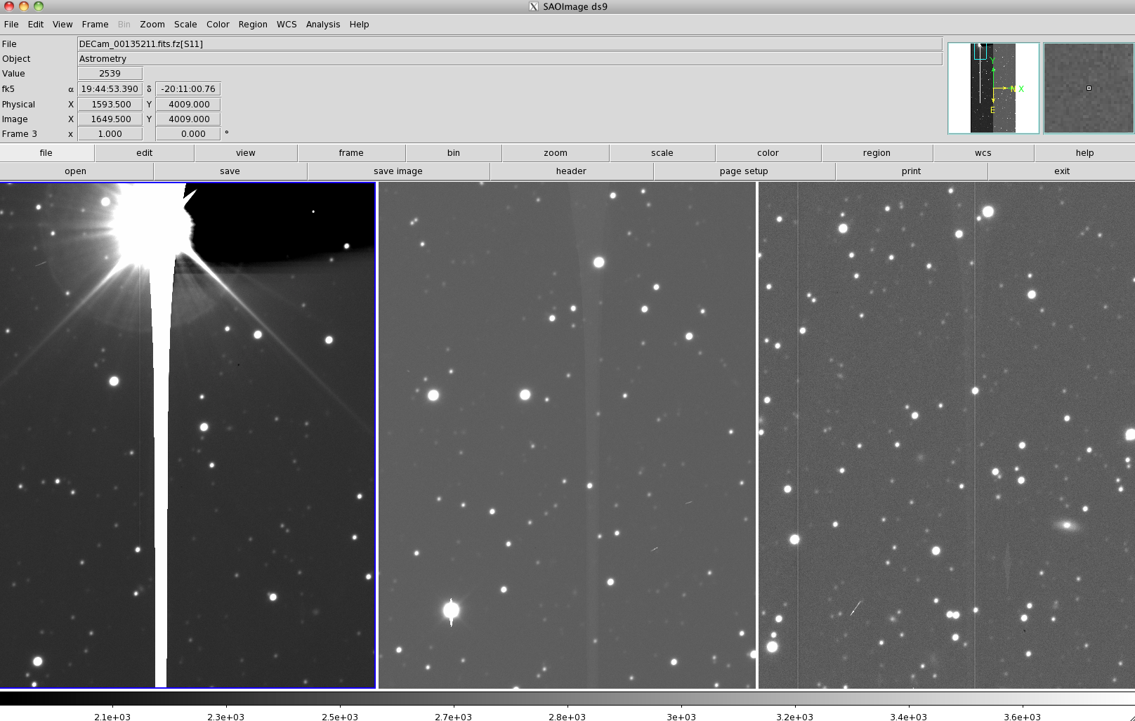
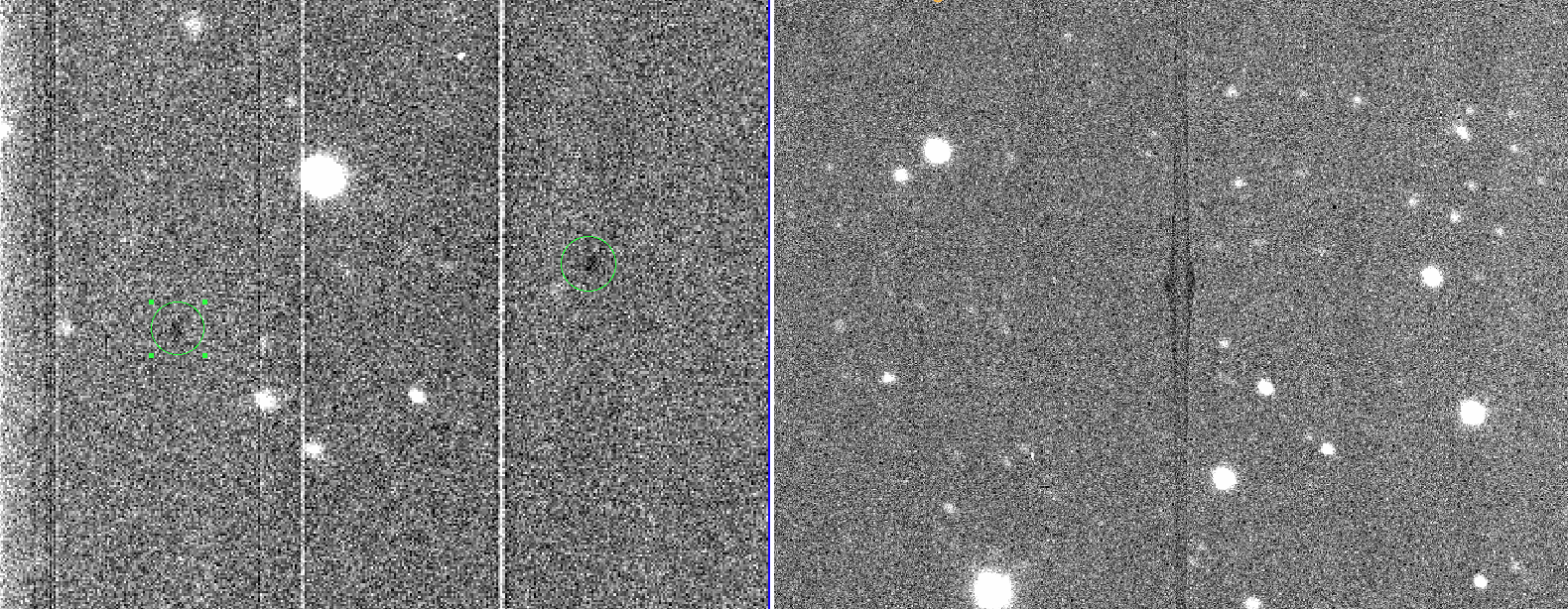
visual example for negative crosstalk
An example for negative crosstalk can be seen on CCD N1 (#32, extension #4) of DECam_com5_00133787
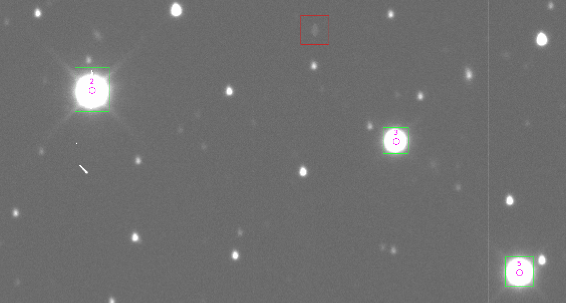
Amplifier A (sources are marked in green, victims in red):
 Amplifier B (victims marked red):
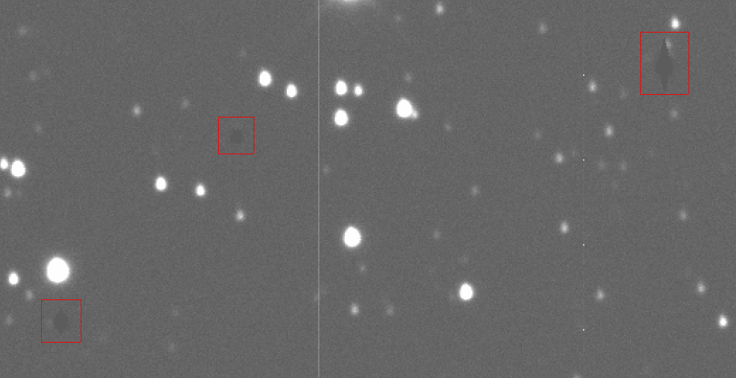 Victims on Amplifier A show positive crosstalk (victim area is brighter), while victims on
Amplifier B show negative crosstalk (victim area is darker).
Victims on Amplifier A show positive crosstalk (victim area is brighter), while victims on
Amplifier B show negative crosstalk (victim area is darker).
source and victim pixels
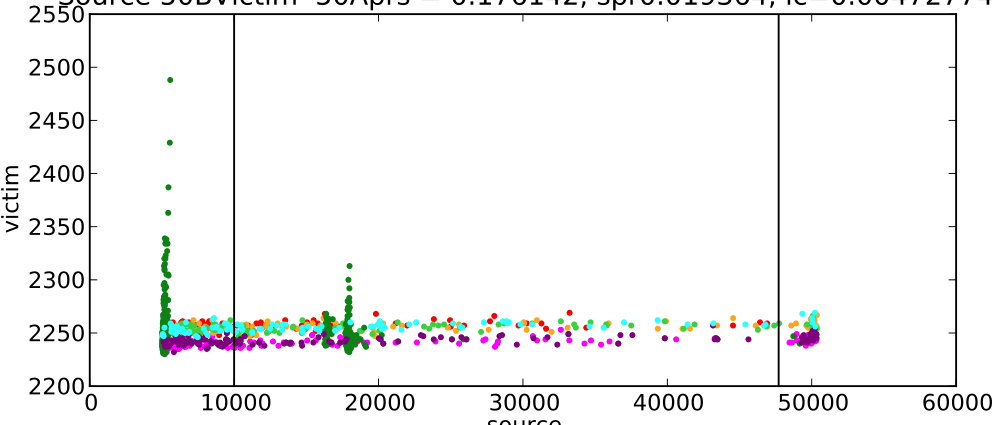
The crosstalk is determined by doing a linear regression to the counts of the victim pixels vs. the source pixels. Dead columns or sources nearby (bright objects as well as cosmics) can produce a bias. Examples for this are show below. Colors of symbols indicate to which source the pixel/count information belongs to.
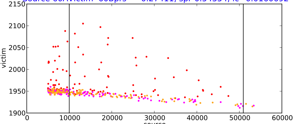
The first two can be nicely cut by using the linear correlation coefficient used by Bill. The last two are not as straight forward.
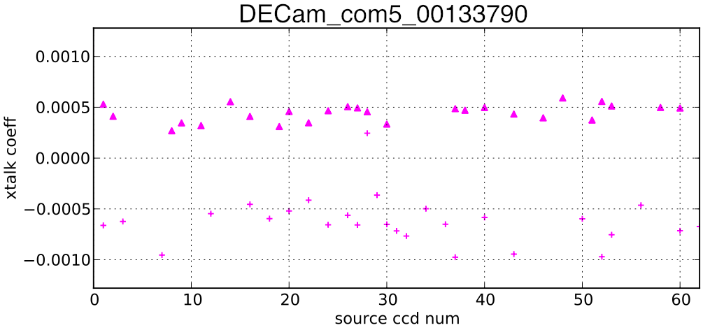
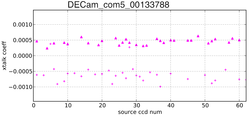
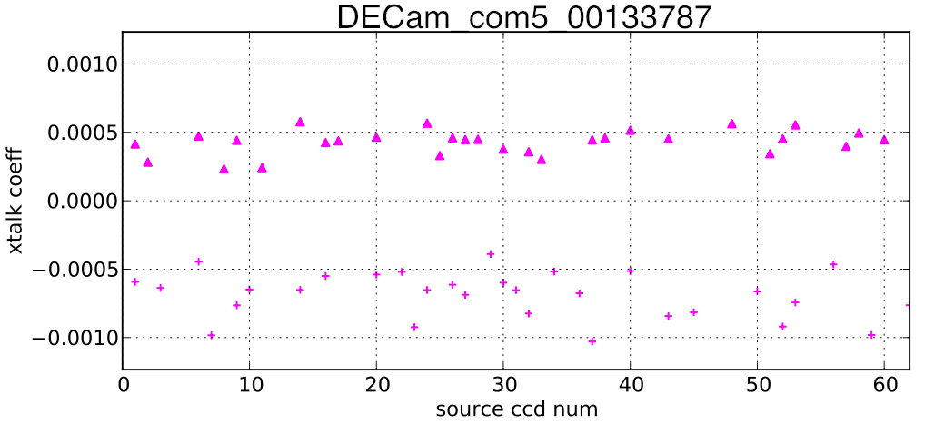
crosstalk for each of the investigated exposures
Source amplifier A is marked with + while amplifier B is marked with triangles.
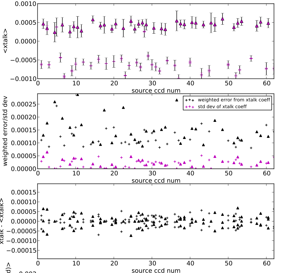
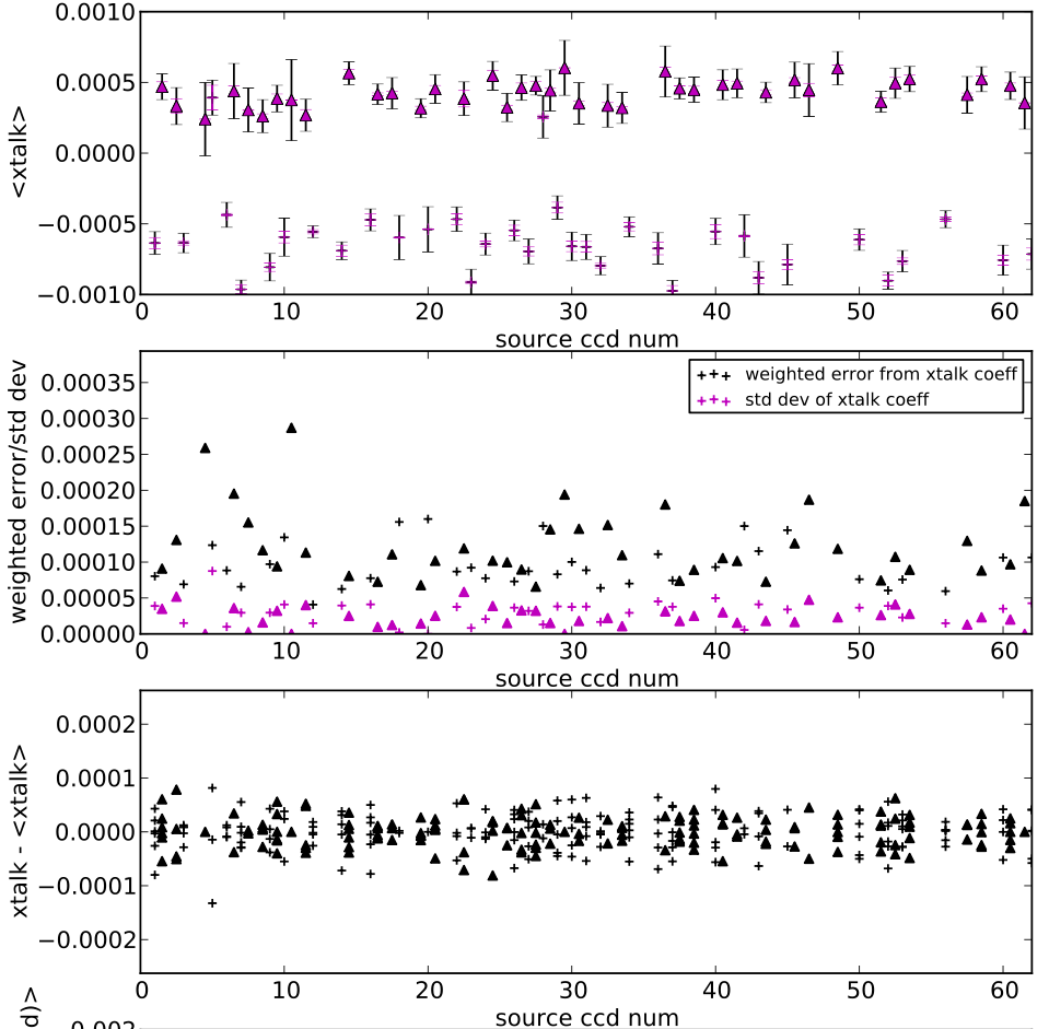
combined crosstalk for 3 exposures used
For most of the source amplifiers, 3 good xtalk fits were available, but a few only had one or two. Errors show are: weighted errors from the linear regression (black) and standard deviation of the xtalk coefficients for a given source amp. First plot shows the average (weighted mean) crosstalk coefficients including errors. Second plot is just the errors described above. The third plot shows the scatter of the coefficients around the weighted mean (for the given amp). The second and third plot will be more meaningful as more exposures are used.
combined crosstalk for exposures 133788 - 133792 (6 exposures)
For intra-ccd crosstalk only
results from robust fitting
Investigated some ways of cleaning up the xtalk coefficients. So far used the pearson correlation coefficient, but that will be small for amp pairs with low crosstalk, so probably will be less helpful. Therefore investigated to use robust fitting methods and cuts to get better results.
Sometimes victim pixel counts are offset for sources (for example bright source nearby) which introduces a large spread for the "global" fit to all sources. Trying to exclude amp pairs where the spread is too large.
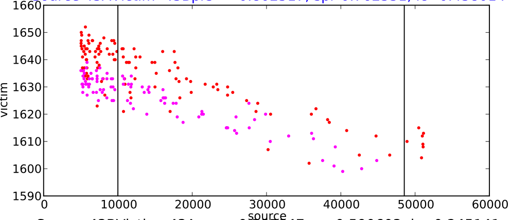
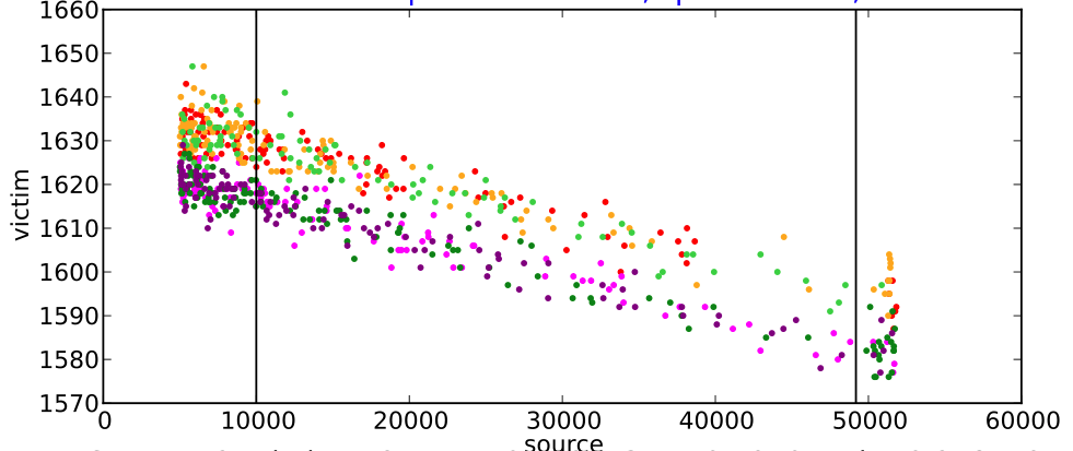
Determine the spread by doing a robust fit to the pixels (a+bx) for each source to determine a. If spread between sources of a is too large then
- either discard the amp pair for the given exposure
- or shift the victim pixels by b and do a fit over all source/victim pixels (yellow symbols)
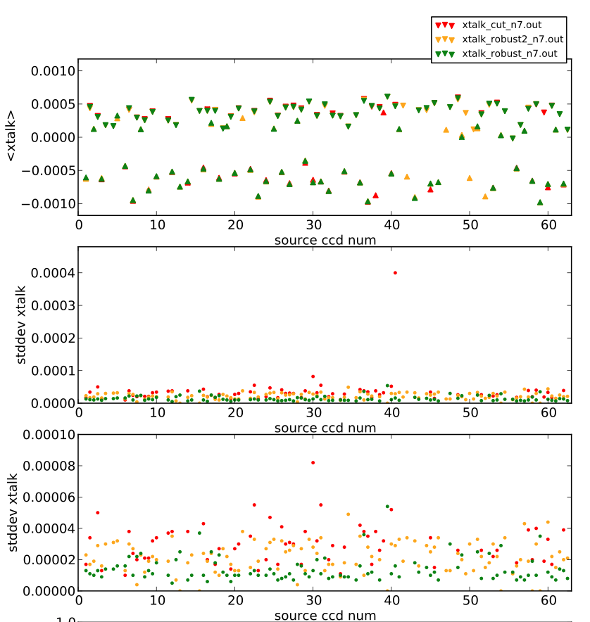
If the spread is low enough, do a robust fit on all the source/victim pixels (green symbols) or use the least square fit results from Bill's code (red symbols)
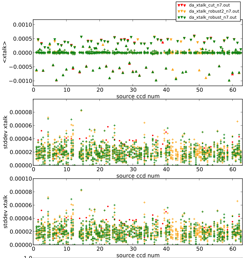
Plots show results where 7 exposures were used.
Results for intra-ccd crosstalk:
Resutls for inter-ccd crosstalk for ccd's on the same DA-board
Ongoing work
- The above analysis has been done in python, but too slow to determine the full xtalk matrix. Working on including the robust fit into Bill's xtalk code right now. Hopefully will be done by tomorrow.
- Could not verify yet if xtalk from N to S ccd's is handled correctly (y-Overscan) - simulations do not cover this properly yet.
- Identified some exposures where inter-ccd crosstalk can be seen.

Results after including robust fitting into xtalk code
method including robust fit
A robust fit is done using l1-norm, i.e. sum(|model(ix)-iy|) is minimized where model = a + b*ix for a fit over all available source/victim pixel pairs. To discard amp pairs with outliers or to large scatter between sources (i.e. the offset between the sources, i.e. a_{i_source} is too large).
cuts done
cuts will remove a rather large number of amplifier pairs for a given exposure (can be on the order of 50%), but will make sure not too many outliers will affect the xtalk measurement.
- only use source pixels with counts 10000 to 0.9*saturate
- source level (source but not entire amp pairing will be discarded)
- at least 10 source/victim pixel pairs
- a range of at least 20000 counts per source
- nmad (robust estimate of scatter) of source pixels > 0.2*(0.9*saturation-10000) to discard
sources that are mostly clustered around a very narrow range. Example:
- amplifier pair level cuts
- at least 3 different sources (have not tested the impact of this cut, so maybe this can be relaxed)
- at least 80 data points (source and victim pixel pairs)
- if scatter of offset between sources is small enough (scatter of offset < 1.5*median scatter of residuals for individual source fits)

Results for commissioning data 20120911
results that pass the cut overall show low scatter, but a lot of amplifier pairs don't pass the the cuts. White area means there are no values for the crosstalk (either due to being the same amplifier or there being no exposures for the amp pair that passed the cut).
x and y axis show the ccd number: 0-61 is amplifier A, 62-123 is amplifier B. Hence the main diagonal is all white as those are the elements for the same amplifier. The colored off-diagonals are the intra-ccd crosstalk.
Used exposures 133787-133806 Figure shows the xtalk coefficients, the standard deviation of the coefficients and the number of xtalk measurements used in the average (that passed the above cuts). Color scale of standard deviation is cut at 1e-4
The crosstalk matrix can be found here, columns are victim and source amp, averaged xtalk coeff, std deviation of individual measurements, number of individual measurements used. Only coefficients > 1e-6 are included. if no xtalk coeff could be determined, all values are not included
Results for 20120924 - a lot noisier
Used exposures 136085-136100 Color scale of standard deviation is cut at 1e-4!!!
The crosstalk matrix can be found here.
Noise is a lot larger - not sure why yet.
Results for 20121002 - exposures 137961 - 138170
- 83 exposures
- Color scale of standard deviation is cut at 1e-4
- still no crosstalk for ccd46…?
The crosstalk matrix (with absolute values larger 1e-6) can be found here.
Combined matrix for nights 20121002, 20121101, and 20121102
- 191 exposures
- full matrix is here
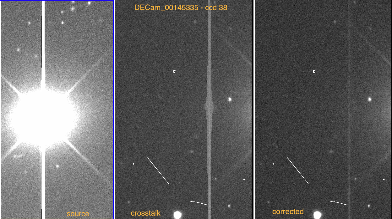
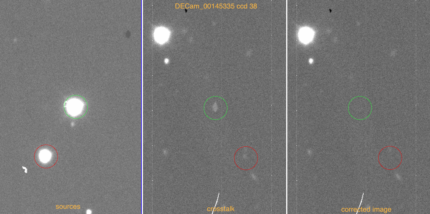
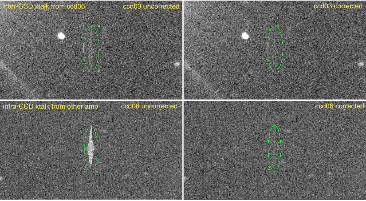
Example exposure: DECam_00146986.fits.fz (night 20121104) - corrections applied (desdmsoft 7.1.1)
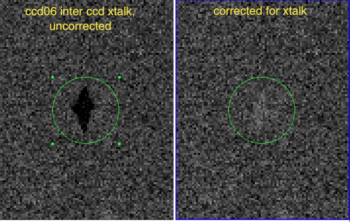
- crosstalk originating from ccd06 (inter and intra ccd)
- files/xtalk_corr_example1.png
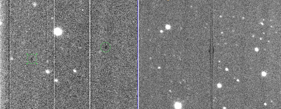
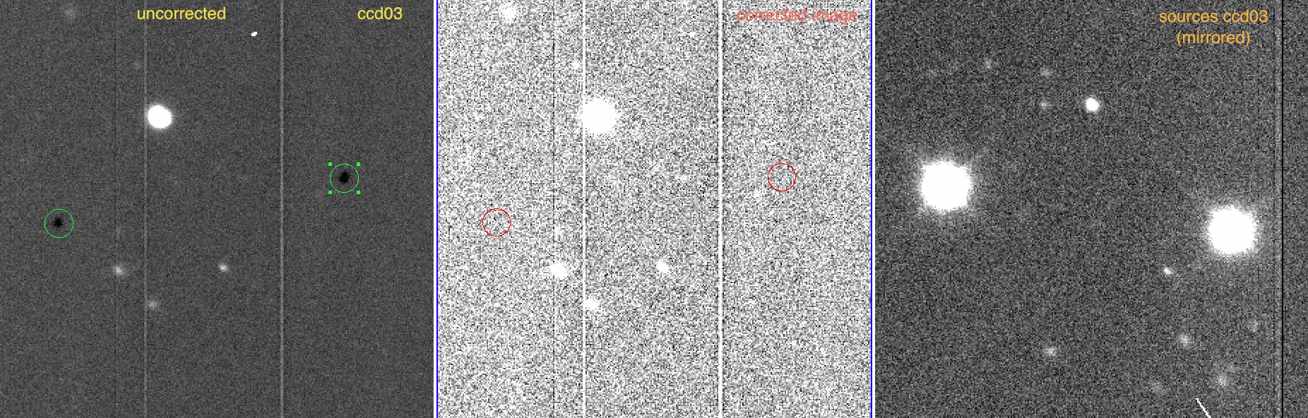
- crosstalk originating from ccd03 (intra ccd)
- some overcorrection, but seems to be occuring for strongly saturated sources (~60 000 cts); though the center is clearly overcorrected, the edges seem to be subtracted fine.
- the same coefficient seems to work fine for other bright sources (~53 000 cts); using the over correction of the bright source as a guidance, we should also see an over correction of about 6-7 cts (sky sigma is about 4-5 cts).
- using a lower (-4.85e-4 instead of -6.11e-4) value to correct for the large source get's the center but not the edges
right. Smaller sources are under-corrected
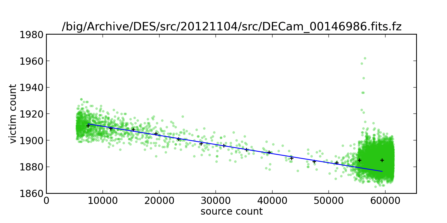
- source vs. victim pixel count for ccd 3 of DECam_00146986.fits.fz; "+" indicate binned median; excess for very large count number
- crosstalk orignating from ccd06 (intra ccd)

Example exposure: DECam_00146986 ccd 38
- same correction applied to different sources